
Project Overview
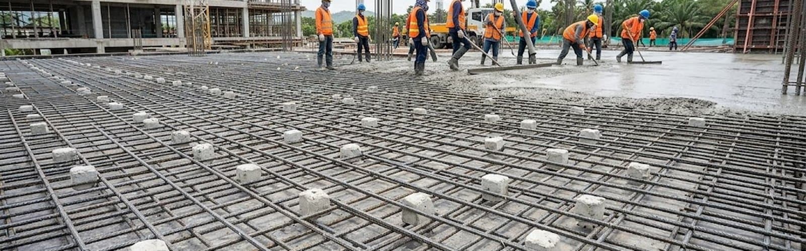
A marine concrete structure on Thailand's eastern coast — comprising pier sections, tank foundations, and retaining walls — sat in both the splash zone and submerged zone of seawater. Chloride penetration was reaching the reinforcing steel and driving accelerated corrosion.
Pre-project half-cell potential readings showed multiple zones in "active corrosion" state (potential >-350 mV vs Cu/CuSO₄). Without intervention, rebar cross-section loss >15% within 3-5 years would have compromised the structural integrity of the entire structure.
Sahawatthanakit (1988) delivered a full turnkey EPC scope — CP system design, anode supply, installation, commissioning, and 1-year post-installation potential survey.
Design Methodology
Step 1 — Corrosion Survey (baseline)
- Half-cell potential mapping across the full 18,000 m² per ASTM C876
- Concrete cover depth measured via rebar locator per BS 1881-204
- Chloride content at rebar depth via core-drill sampling
- Concrete resistivity measured with 4-pin Wenner probe per ASTM G57
Result: 67% of the structure showed chloride content >0.4% by mass of cement (the active-corrosion threshold).
Step 2 — Anode Selection + Sizing
Galvanic Zinc Anode was selected over Impressed Current for these reasons:
- No external power required = zero maintenance + zero electricity cost over service life
- Inherently safer in a marine environment — no exposed high-voltage circuits
- Designed for 25-30 year life per Faraday's law:
Anode life = (Anode weight × Faraday efficiency × Hours/year) / (Current output × Equivalent weight)
Step 3 — Engineering Calculation (ISO 12696)
- Design current density: 20 mA/m² (atmospheric zone), 25 mA/m² (splash zone)
- Anode capacity: ASTM B418-21 Type II zinc — 815 A·h/kg
- Anode spacing: 600-900 mm based on current distribution analysis
- Throwing distance (effective protection radius) — verified via FEM modeling
Installation
| Parameter | Specification |
|---|---|
| Anode type | Galvanic Zinc — pellet wrapped in low-pH backfill |
| Anode count | 2,400 across 18,000 m² (density 1 anode per 7.5 m²) |
| Embedment depth | 50-75 mm below concrete surface (between outer cover and first rebar layer) |
| Connection | Stainless steel braided cable + crimp connector + heat-shrink seal |
| Test stations | 24 points across structure for potential verification |
| Patch repair | Per ICRI 320.2R + bonding agent at anode locations |
| Commissioning | Half-cell potential survey 30 days post-installation as baseline |
| Installation duration | 8 weeks |
Results (18-month monitoring data)
| Metric | Baseline | Current |
|---|---|---|
| Half-cell potential | -380 to -520 mV (active corrosion) | -250 to -310 mV (passive zone) |
| Rebar corrosion rate | >25 μm/year | <0.5 μm/year |
| Test stations passing 100mV decay criterion | — | 100% (24/24) |
| Anode consumption (18 months) | — | 3.8% of total mass → projected 25-30 yr life |
| Long-term savings vs Impressed Current | — | ~฿800K-1.2M per 10 years (no power + no rectifier maintenance) |
Why the Client Chose Us
- ISO 12696-compliant engineering design — not rule-of-thumb; complete Faraday + FEM analysis
- ASTM B418 + TIS 3029-2563 certified anodes — CoA + chemical composition per lot
- Maintenance-free — galvanic system = no rectifier service
- Full EPC scope — design + supply + install + commissioning + 1-year post-installation survey
- Comparable case studies — prior marine + bridge cathodic protection experience
Related Services
Looking for Galvanic or Impressed Current Cathodic Protection for reinforced concrete structures — factories, bridges, piers, tanks, parking decks? Our engineering team will conduct a free site survey + half-cell potential mapping before quoting.
Learn more: Cathodic Protection Service
Technical reading: Concrete Anode Cathodic Protection — Technology and Selection